
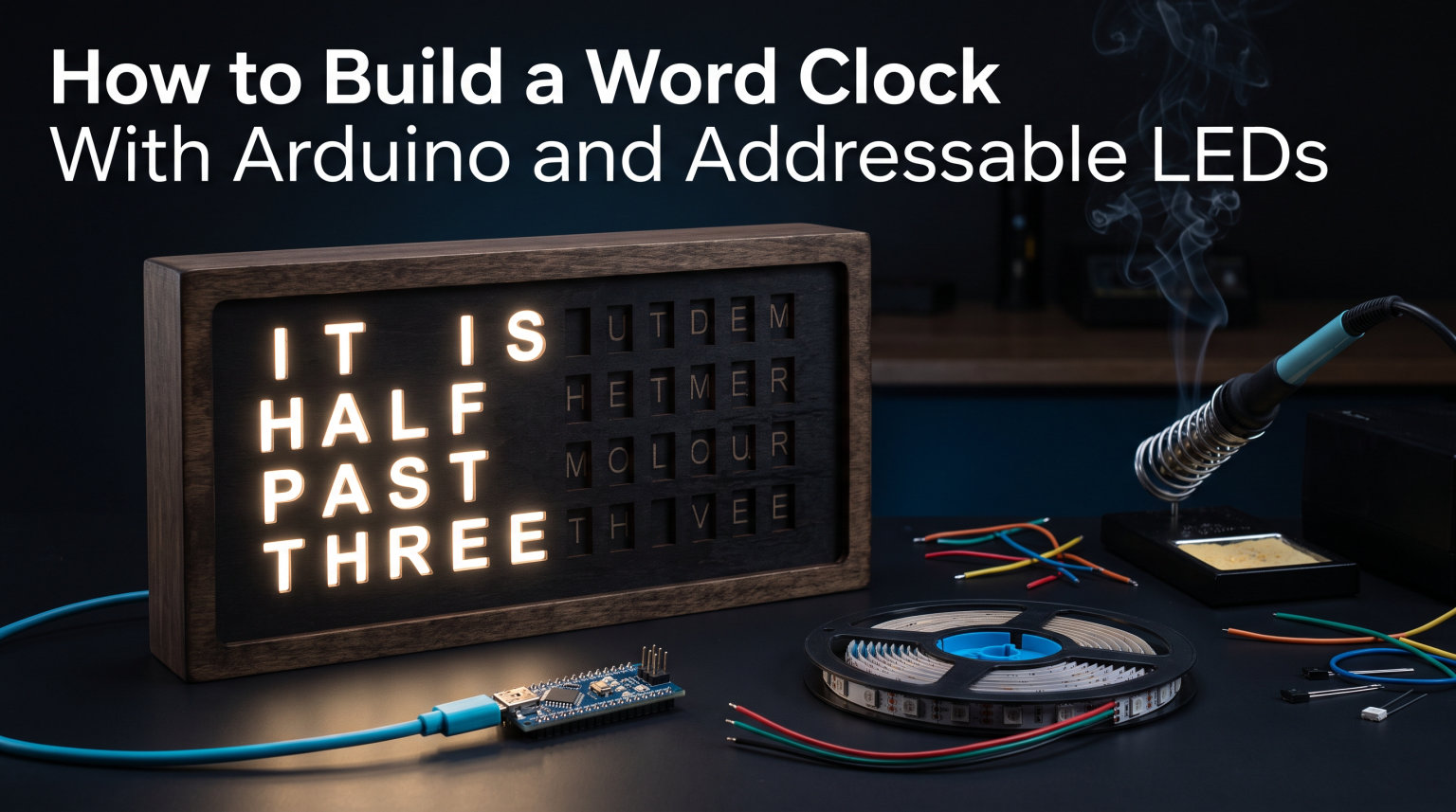
Building an Arduino word clock is one of the most rewarding DIY electronics projects you can tackle. Instead of showing digits like a normal clock, a word clock spells out the time in actual words — “IT IS HALF PAST TEN” — using addressable LEDs hidden behind a letter grid. The result is part timepiece, part wall art, and entirely satisfying to build.
In this guide, I will walk you through every step of the process, from gathering components to writing the Arduino sketch and assembling the final display. Whether you are new to Arduino or have a few projects under your belt, this tutorial covers everything you need with no guesswork left out.
The Arduino word clock combines three core skills: electronics wiring, Arduino programming, and basic craftsmanship for the display panel. I have broken this build into clear, numbered steps so you can follow along at your own pace and troubleshoot issues as they come up.
By the end, you will have a working clock that keeps accurate time using a real-time clock module, lights up words using WS2812B addressable LEDs, and looks like something you would buy from a high-end design store.
Table of Contents
How an Arduino Word Clock Works
An Arduino word clock works by reading the current time from a real-time clock module and then turning on specific LEDs that sit behind a grid of letters cut into a front panel. The Arduino acts as the brain, deciding which LEDs to light based on what time it is.
Here is the process in simple terms. The DS3231 RTC module keeps track of time even when the Arduino loses power, thanks to its built-in battery backup. The Arduino reads this time over an I2C connection every second. It then checks which words need to be illuminated to express the current time — for example, “IT IS,” “QUARTER,” and “PAST” plus the current hour.
Each word on the front panel maps to one or more LEDs in a strip. The Arduino sends a data signal to the first LED in the chain, and each LED passes the signal along to the next. This is what makes WS2812B (also called Neopixel) LEDs so powerful — you can control dozens of individual LEDs using a single data pin on the Arduino.
The front panel features a grid of letters, typically 11 columns by 10 rows. When you look at the clock, you only see the words that are lit up. The unlit letters blend into the background, creating that clean, minimal aesthetic that makes word clocks so striking.
Complete Components List for Your Arduino Word Clock
Building an Arduino word clock requires a specific set of components. Here is every part you need, with the exact specifications that will work for a standard 11×10 grid build using roughly 100 addressable LEDs.
Core Electronics
Arduino board (Arduino Uno, Nano, or Pro Mini): The Uno is the easiest starting point for beginners because of its built-in USB programming and generous pin count. The Nano or Pro Mini work better if you want a compact final enclosure. Any 5V Arduino with at least one digital pin and I2C support will work.
WS2812B addressable LED strip (1 meter, 60 LEDs per meter, or individual LED matrix): You need approximately 100 individual LEDs for a standard word clock grid. A single 60-LED-per-meter strip gives you 60 LEDs, so plan for two strips or buy a pre-built flexible matrix. WS2812B LEDs are preferred because each LED has its own built-in controller chip, letting you address them individually with one data wire.
DS3231 RTC module: This is the real-time clock that keeps time even during power outages. The DS3231 is temperature-compensated, meaning it stays accurate to within a few minutes per year. It connects to the Arduino via just two wires using the I2C protocol.
5V 2A (or higher) power supply: Addressable LEDs draw significant current. At full white brightness, each WS2812B LED pulls about 60 milliamps. With 100 LEDs at full power, you need up to 6 amps. However, since a word clock only lights a fraction of its LEDs at any time and rarely at full white, a 5V 2A supply handles most builds comfortably. A 5V 4A supply gives you headroom for brighter colors.
Supporting Components
470 ohm resistor: Placed in series on the data line between the Arduino and the first LED. This protects the LED data input from voltage spikes and signal ringing.
1000 microfarad, 6.3V capacitor: Placed across the power rails to smooth out voltage fluctuations when large numbers of LEDs turn on or off simultaneously.
Jumper wires and a breadboard (or protoboard): For making temporary connections during testing. You can solder everything to a protoboard for a permanent build.
CR2032 coin cell battery: Powers the DS3231 RTC module’s backup so it remembers the time when main power is disconnected.
Display and Enclosure Materials
Front panel material: Black foam board, laser-cut MDF, or 3D-printed panels work well. The panel needs precise cutouts or a printed letter grid that allows light to pass through individual letters.
Diffuser material: Frosted acrylic sheet, tracing paper, or white polypropylene behind the letter grid. The diffuser spreads each LED’s light evenly so letters glow cleanly without hotspots.
Enclosure: A picture frame, wooden box, or 3D-printed case to hold everything together. An IKEA RIBBA frame is a popular budget option that fits a standard word clock layout.
RTC Module Comparison: DS3231 vs DS1307 vs PCF8523
Choosing the right real-time clock module is one of the most important decisions for your Arduino word clock. The RTC determines how accurate your clock stays over time. Three modules dominate the DIY space, and they are not created equal.
DS3231: This is the gold standard for DIY clock projects. It is temperature-compensated, meaning it adjusts for thermal drift automatically. Expect accuracy within plus or minus 2 minutes per year. It includes a built-in crystal oscillator, so you never deal with the external crystal frequency issues that plague cheaper modules. This is the module I recommend for every word clock build.
DS1307: This older module was the go-to choice for years, but it relies on an external crystal oscillator that is sensitive to temperature changes. Forum users on r/arduino consistently report drift of several minutes per month with the DS1307. It also requires a separate battery to keep time. For a word clock that you want to set and forget, the DS1307 is not the best choice.
PCF8523: This module from Adafruit offers middle-ground accuracy. It drifts about 10 to 20 seconds per month in typical conditions. It draws very little power and works well for low-power projects. However, for a word clock that runs continuously, the DS3231’s superior accuracy makes it worth the small additional cost.
The bottom line: spend the extra dollar or two on the DS3231. Your word clock will keep better time, and you will avoid the frustration of constantly adjusting it.
Power Supply Requirements and Calculations
Power is the most commonly misunderstood part of building an Arduino word clock. Get this wrong and you will experience flickering LEDs, random resets, or a clock that simply does not turn on. Here is how to calculate exactly what you need.
Each WS2812B LED draws approximately 60 milliamps at full brightness on pure white (20 milliamps each for red, green, and blue). For a 100-LED word clock, full white at maximum brightness would draw 6 amps. That is significant power.
In practice, a word clock never lights all 100 LEDs at once. A typical time display activates 15 to 25 LEDs, and you rarely use pure white. If you display warm colors at 50 percent brightness, your actual draw stays under 1 amp for most of the day.
Here is my recommendation based on LED count. For a build with 60 LEDs or fewer, a 5V 2A power supply is sufficient. For 61 to 100 LEDs, use a 5V 3A supply to give yourself headroom. For builds exceeding 100 LEDs, go with 5V 4A or higher. Never power more than 30 LEDs directly from the Arduino’s 5V pin, as the onboard regulator cannot handle that current.
Always connect your power supply directly to the LED strip’s power input, not through the Arduino. Run a separate wire from the power supply to the Arduino’s 5V pin (or Vin pin if using a higher voltage supply with a regulator). This keeps the high current path away from the Arduino’s traces.
Wiring the Circuit: Step-by-Step Connections
Wiring your Arduino word clock correctly is critical. One wrong connection can prevent the LEDs from lighting or damage your components. Follow these steps in order, and test each section before moving on.
Step 1: Wiring the DS3231 RTC Module
The DS3231 communicates with the Arduino using the I2C protocol, which requires only two data wires plus power and ground. Connect the RTC module’s VCC pin to the Arduino’s 5V pin. Connect GND to any GND pin on the Arduino.
Connect the SDA pin on the RTC module to the Arduino’s SDA pin (A4 on the Uno and Nano). Connect the SCL pin to the Arduino’s SCL pin (A5 on the Uno and Nano). These two pins carry all the time data between the RTC and the Arduino.
Insert the CR2032 battery into the RTC module before powering up. This ensures the module starts keeping time immediately.
Step 2: Wiring the WS2812B Addressable LEDs
Connect your 5V power supply’s positive output to the 5V pad on the LED strip. Connect the power supply’s ground to the GND pad on the LED strip. Also connect this same ground to a GND pin on the Arduino — all components must share a common ground.
Place the 470 ohm resistor on the data line between the Arduino’s digital pin 6 and the DIN (data input) pad on the LED strip. The resistor goes as close to the first LED as possible. This prevents signal integrity issues that cause flickering.
Place the 1000 microfarad capacitor across the 5V and GND pads on the LED strip. The negative leg of the capacitor (shorter leg, marked with a stripe) connects to GND, and the positive leg connects to 5V. This capacitor absorbs sudden current spikes when many LEDs switch on at once.
Step 3: Power Distribution Check
Before connecting anything to power, double-check these connections. The Arduino and LED strip share a common ground. The data line from pin 6 passes through the 470 ohm resistor. The capacitor is correctly oriented with positive to 5V and negative to GND. The power supply outputs 5V DC (not higher).
If you are powering the Arduino from the same 5V supply as the LEDs, connect the supply’s 5V output to the Arduino’s 5V pin directly. Do not use the Vin pin for a 5V supply, as Vin expects 7 to 12 volts and passes through a regulator that would drop the voltage too low.
Setting Up the DS3231 RTC Module
Before your word clock can display the time, the RTC module needs to be set to the correct time. This is a one-time setup process that programs the current time into the module’s memory. After that, the battery backup keeps the time accurate even through power cycles.
Step 1: Install the Required Libraries
Open the Arduino IDE and install the RTCLib library by Adafruit. Go to Sketch, then Include Library, then Manage Libraries. Search for “RTClib” and install the version by Adafruit. This library handles all communication with the DS3231 over I2C.
You also need the Adafruit Neopixel library for controlling the WS2812B LEDs. Search for “Adafruit NeoPixel” in the Library Manager and install it.
Step 2: Find the RTC I2C Address
Most DS3231 modules use the I2C address 0x68. If you are not sure, run an I2C scanner sketch (available in the Arduino examples) to detect the address automatically. Some modules with alternate configurations may use 0x57 for the built-in EEPROM, but the RTC itself is almost always at 0x68.
Step 3: Set the Time
Upload the “ds1307” example sketch that comes with RTClib (it works with the DS3231 as well). This sketch sets the RTC to the compile time of your sketch — meaning the exact time and date shown on your computer when you click upload. Open the Serial Monitor at 9600 baud after uploading to verify the RTC is reading correctly.
Once confirmed, comment out the line that sets the time (RTC.adjust) and re-upload. This prevents the clock from resetting every time you power cycle the Arduino. The RTC now holds the correct time independently.
Designing the Word Layout and LED Grid
The word layout is the heart of your Arduino word clock’s design. This is the letter grid that sits on the front panel, and each letter maps to a specific LED position. Getting this mapping right determines whether your clock displays the correct words.
Choosing a Grid Size
The most common English word clock layout uses an 11-column by 10-row grid, giving you 110 letter positions. This provides enough space to spell out hours, minutes in five-minute increments, and filler words like “IT IS” and “O’CLOCK.”
A typical English grid starts with “IT IS HALF TEN” in the first row, followed by “QUARTER TWENTY” in the second, “FIVE MINUTES PAST” in the third, and so on through all twelve hours. The exact arrangement depends on your language and how many minute intervals you want to display.
Mapping Words to LED Indices
Each LED in your strip has a sequential index number starting from 0. The first LED in the data chain is index 0, the second is index 1, and so on. You need to map each word to the specific LED indices that illuminate its letters.
For example, if the word “IT” occupies positions behind LED index 0 and 1, and “IS” occupies indices 2 and 3, you define arrays in your code: wordIT contains {0, 1} and wordIS contains {2, 3}. When the clock needs to display “IT IS,” the Arduino turns on all four of those LEDs.
This mapping is the most tedious part of the build, but it is also the most important. Take your time laying out the grid on paper or in a spreadsheet before transferring it to code. Measure twice, wire once.
The Complete Arduino Word Clock Sketch
Here is the complete Arduino sketch that ties everything together. This code reads the time from the DS3231, determines which words to illuminate, and controls the WS2812B LEDs. I have annotated every section so you understand what each part does.
Start by including the necessary libraries and defining your LED and pin constants:
#include <Wire.h>
#include “RTClib.h”
#include <Adafruit_NeoPixel.h>
#define LED_PIN 6
#define NUM_LEDS 100
#define BRIGHTNESS 40
Adafruit_NeoPixel strip = Adafruit_NeoPixel(NUM_LEDS, LED_PIN, NEO_GRB + NEO_KHZ800);
RTC_DS3231 rtc;
Next, define your word-to-LED index mappings. Each array lists the LED indices that make up that word:
int wordIT[] = {0, 1};
int wordIS[] = {2, 3};
int wordHALF[] = {4, 5, 6, 7};
int wordTEN[] = {8, 9, 10};
int wordQUARTER[] = {11, 12, 13, 14, 15, 16, 17};
int wordTWENTY[] = {18, 19, 20, 21, 22, 23};
int wordFIVE_M[] = {24, 25, 26, 27};
int wordMINUTES[] = {28, 29, 30, 31, 32, 33, 34};
int wordPAST[] = {35, 36, 37, 38};
int wordTO[] = {39, 40};
int hourWords[12][10] = { /* LED indices for each hour word */ };
In the setup function, initialize the LED strip and RTC:
void setup() {
strip.begin();
strip.setBrightness(BRIGHTNESS);
strip.show();
if (!rtc.begin()) {
while (1);
}
}
The main loop reads the time and updates the display. It calculates which minute interval applies (rounded to the nearest 5 minutes), determines whether to show “PAST” or “TO,” and lights the corresponding words:
void loop() {
DateTime now = rtc.now();
int hour = now.hour();
int minute = now.minute();
strip.clear();
displayTime(hour, minute);
strip.show();
delay(10000);
}
The displayTime function contains the logic that maps hour and minute values to specific word arrays, then calls a helper function to light each word’s LEDs. This is where you implement the five-minute rounding and “to” versus “past” logic.
Adjust the BRIGHTNESS value to control overall LED intensity. A value of 40 out of 255 is a good starting point that keeps power draw low and prevents the clock from being blindingly bright in a dark room.
Building the Display: Diffuser and Enclosure
The electronics are only half the build. The display panel and enclosure are what transform your Arduino word clock from a breadboard experiment into a polished piece of decor. The diffuser is the single most important element for achieving that clean, professional look.
Choosing a Diffuser Material
The diffuser sits between the LEDs and the letter grid, spreading each LED’s light so the letters glow evenly. Without a diffuser, you see harsh individual LED points through each letter, which looks cheap and is hard to read.
Frosted acrylic is the best diffuser material for a permanent build. A 3mm frosted acrylic sheet diffuses light evenly and is rigid enough to mount securely. You can buy it pre-frosted or frost clear acrylic yourself with fine sandpaper.
For a budget option, tracing paper or white tissue paper works surprisingly well. Layer two or three sheets to achieve the right level of diffusion. The downside is that paper is fragile and may yellow over time.
White polypropylene sheets offer a middle ground. They diffuse well, are inexpensive, and last longer than paper. Many makers report good results with a single 1mm polypropylene sheet.
Building the Letter Grid
Print your letter grid on paper and use it as a template. If you have access to a laser cutter, cut the letters directly into black acrylic or MDF for the cleanest result. For a manual approach, print the grid on dark cardstock and use a craft knife to cut out each letter window.
Layer the components from back to front: LED strip mounted on a backing board, then the diffuser material, then the letter grid panel, then a clear protective front sheet if desired. Secure everything in a frame or enclosure.
Enclosure Options
An IKEA RIBBA or HOVSTA picture frame is the most popular budget enclosure. Remove the glass, install your layered display, and close it up. These frames come in sizes that fit a standard word clock layout perfectly.
For a custom look, 3D-printed enclosures offer complete control over dimensions and design. You can find STL files on Thingiverse and Printables designed specifically for word clock builds. A wooden box made from pine or plywood gives a warm, handcrafted feel.
Adding Automatic Brightness Control with an LDR
A word clock that blazes at full brightness all night is annoying. Adding an LDR (light-dependent resistor) lets your Arduino word clock dim itself automatically based on ambient room light. This is a simple upgrade that significantly improves the user experience.
Wire the LDR in a voltage divider circuit with a 10K resistor. Connect one leg of the LDR to 5V and the other leg to analog pin A0. Connect the 10K resistor between A0 and ground. The Arduino reads the voltage at A0, which changes based on how much light hits the LDR.
In your code, read the analog value from A0, map it to a brightness range (for example, 10 to 80), and call strip.setBrightness() with the result. Add a small delay or averaging filter to prevent brightness from flickering when light levels fluctuate slightly. This keeps the clock readable during the day and gently glowing at night.
Testing and Troubleshooting Your Word Clock
Even with careful planning, you will likely encounter issues during your build. Here are the most common problems and their solutions, based on real experiences from Arduino forums and maker communities.
Problem: No LEDs Light Up
If none of your LEDs turn on, check the power supply first. Measure the voltage at the LED strip’s power pads with a multimeter — it should read close to 5V. If the voltage is low or zero, your power supply may be disconnected or faulty.
Next, verify the data connection. Ensure the data wire goes from Arduino pin 6 through the 470 ohm resistor to the DIN pad on the LED strip, not the DOUT pad. The DIN pad is the input — connecting to DOUT means the signal goes nowhere.
Finally, check that all grounds are connected. The Arduino, LED strip, and power supply must share a common ground. A missing ground connection is the most common cause of completely dark LEDs.
Problem: RTC Loses Time or Shows Wrong Time
If your clock displays the wrong time or resets to a default date, the RTC module is not holding time. First, check that the CR2032 battery is installed and has charge. A dead battery means the RTC forgets the time whenever power is removed.
Verify your I2C connections. Swap the SDA and SCL wires by accident and the RTC will not communicate at all. Run the I2C scanner sketch to confirm the Arduino can see the module at address 0x68.
If the time is set but drifts significantly, you may be using a DS1307 instead of a DS3231. The DS1307’s external crystal is temperature-sensitive and can drift minutes per month. Upgrading to the DS3231 solves this permanently.
Problem: LEDs Light Up in Wrong Pattern or Colors
If your LEDs turn on but show unexpected colors or light up in the wrong positions, the issue is in your word-to-LED mapping. Double-check that your index arrays match the physical LED positions behind each word.
LEDs that show the wrong color (green when you expect white, for example) usually indicate a color order mismatch. Try changing NEO_GRB to NEO_RGB or NEO_RGBW in your strip initialization. Different LED batches use different color orders.
Problem: Flickering or Unstable LEDs
Flickering usually points to a power or signal issue. Ensure the 1000 microfarad capacitor is installed across the power rails. Verify the 470 ohm resistor is on the data line. If flickering persists, your power supply may be underpowered — check that it can deliver enough current for the number of LEDs you are illuminating.
Long data wires can also cause flickering. Keep the wire between the Arduino and the first LED as short as possible, ideally under 30 centimeters. If you need a longer run, use a logic level shifter to boost the data signal to a clean 5V.
Problem: Ghosting or Light Bleed Between Letters
Ghosting happens when light from one LED bleeds into adjacent letter positions. This is a diffuser or spacing issue, not a code problem. Add an additional layer of diffuser material, or increase the distance between the LEDs and the letter grid.
For the cleanest result, create physical light barriers between letter cells. Some makers use a honeycomb grid or individual compartments behind each letter to prevent light bleed. This takes more effort but produces a professional-looking result.
FAQs
How do I control WS2812B LEDs with Arduino?
Control WS2812B LEDs with Arduino using the Adafruit NeoPixel library. Connect the LED strip data input to a digital pin through a 470 ohm resistor, power the strip with a 5V supply, and share a common ground. Initialize the strip with Adafruit_NeoPixel(), set colors per LED with strip.setPixelColor(), and call strip.show() to update the display.
What components do I need for an Arduino word clock?
You need an Arduino board (Uno, Nano, or Pro Mini), a WS2812B addressable LED strip (approximately 100 LEDs), a DS3231 RTC module, a 5V 2A or higher power supply, a 470 ohm resistor, a 1000 microfarad capacitor, jumper wires, a CR2032 battery, and materials for the display panel and diffuser.
How to make a diffuser for LED word clock?
Use frosted acrylic sheet (3mm) for the best results, or layer 2 to 3 sheets of tracing paper for a budget option. White polypropylene also works well. The diffuser sits between the LEDs and the letter grid to spread light evenly and prevent harsh LED hotspots from showing through individual letters.
How to program DS3231 RTC module with Arduino?
Install the Adafruit RTClib library, connect the DS3231 to the Arduino SDA and SCL pins, then upload the ds1307 example sketch to set the time to your computer’s compile time. Verify the time in the Serial Monitor, then comment out the RTC.adjust line and re-upload so the time persists across power cycles.
Why is my Arduino word clock not working?
The most common causes are missing common ground connections, data wire connected to the wrong LED pad (DOUT instead of DIN), insufficient power supply current, dead RTC battery, or incorrect LED index mapping in code. Check power voltage with a multimeter, verify all wiring, and run an I2C scanner to confirm the RTC is detected.
Can I use Neopixels instead of WS2812B for a word clock?
Yes, Neopixel is Adafruit’s brand name for WS2812B-compatible addressable LEDs. They use the same data protocol and work identically with the Adafruit NeoPixel library. Any WS2812B, WS2811, SK6812, or Neopixel strip will work for an Arduino word clock project.
Wrapping Up Your Arduino Word Clock Build
Building an Arduino word clock with addressable LEDs is a project that rewards patience and attention to detail. You have learned how to wire a DS3231 RTC module for accurate timekeeping, connect WS2812B LEDs through a single data pin, write the Arduino sketch that maps time to words, and build a clean display with proper diffusion. Each of these steps builds on foundational skills that transfer to countless other Arduino projects.
The beauty of this build is its flexibility. Once you have the basic word clock working, you can add features like automatic brightness control, RGB color cycling, custom word layouts for different languages, or even Wi-Fi connectivity with an ESP8266 or ESP32. The core architecture stays the same.
Start with the component list, wire carefully, test each section before moving on, and take your time with the word-to-LED mapping. Your finished Arduino word clock will be a conversation piece that tells time in the most elegant way possible — one that you built yourself.