
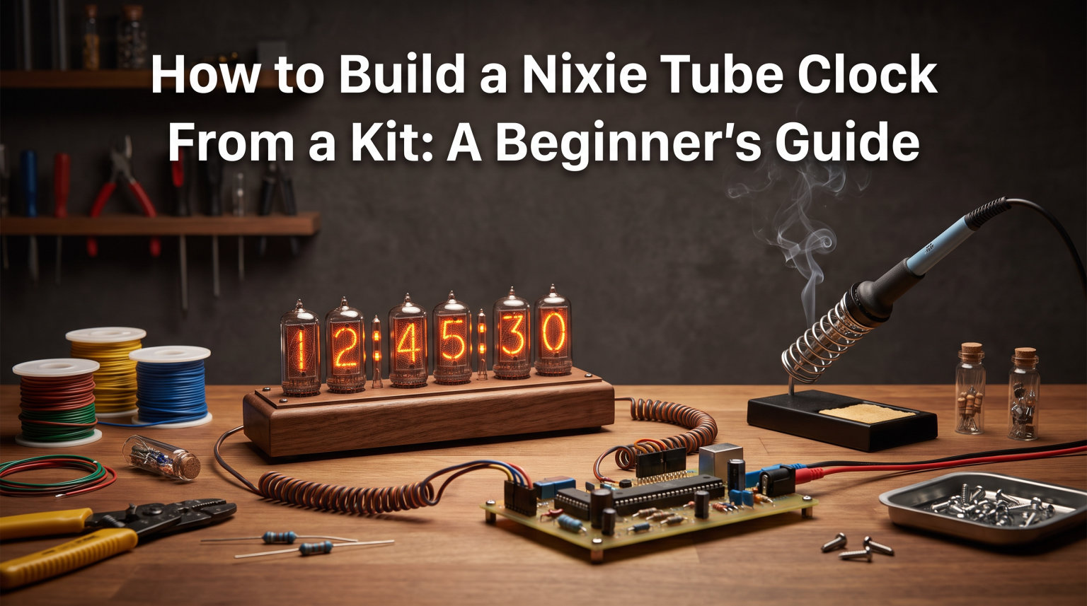
I still remember the first time I plugged in a nixie tube clock I built from a kit. Those warm orange digits glowing to life in my dark workshop felt like pure magic after eight hours of soldering. If you are reading this, you probably want that same feeling, and I am here to tell you it is absolutely within reach even if you have never touched a soldering iron before.
This guide covers everything you need to complete a nixie tube clock kit build from start to finish. I will walk you through selecting the right kit, gathering tools, soldering each component safely, testing as you go, and troubleshooting problems when things do not work the first time.
Learning how to build a nixie tube clock from a kit is one of the most rewarding beginner electronics projects you can take on. The combination of vintage glow, hands-on soldering practice, and a functional timepiece at the end makes every frustrating moment worth it. Let us get into it.
Table of Contents
What Is a Nixie Tube Clock?
A nixie tube clock is an electronic timekeeping device that displays numbers using nixie tubes, which are cold cathode gas discharge indicators that glow with a distinctive warm orange light when activated. Each tube contains ten stacked cathodes shaped like the digits zero through nine, and only one digit glows at a time based on which cathode receives power.
The tubes work through a process called gas ionization. When roughly 170 volts is applied between the anode mesh and a specific cathode wire, the neon gas mixture inside the sealed glass envelope ionizes and produces an orange glow around that digit. The effect looks like a glowing number floating inside the glass, something no LED or LCD display can truly replicate.
Nixie tubes were invented in the 1950s and became the dominant numeric display technology for scientific instruments, early calculators, and industrial equipment through the 1960s and early 1970s. They were eventually replaced by cheaper, smaller, and lower-power seven-segment LED displays.
So why are nixie tubes no longer made? Production stopped almost entirely by the early 1990s because LEDs and LCDs were dramatically cheaper to manufacture, consumed far less power, and lasted longer in commercial applications. The tubes you buy today are mostly New Old Stock (NOS) from factories in the former Soviet Union, which is why genuine tubes carry a premium price.
Hobbyists and collectors prize nixie clocks for their unique vintage aesthetic and the satisfying tactile experience of building something that literally glows. No modern display technology matches the depth and warmth of a real nixie digit.
Is a Nixie Tube Clock Kit Build Right for You?
A nixie tube clock kit build is ideal for beginners who want a first serious electronics project, but you should understand the commitment before buying anything. The good news is that you do not need advanced experience, just patience and a willingness to follow instructions carefully.
The skills required are comfortable through-hole soldering and the ability to follow a build order step by step. If you have never soldered before, I recommend practicing on a cheap perfboard kit for an hour or two first. The joints on a nixie clock need to be clean and reliable because high voltage flows through them.
Plan for a total time commitment of eight to fifteen hours for your first build, spread across multiple sessions. Rushing leads to mistakes, and mistakes on a high-voltage circuit can destroy expensive tubes or create safety hazards. My first build took me three evenings because I stopped to double-check every joint.
If you want a quick weekend project with instant results, a nixie clock is not the right starting point. But if you want a build that teaches you real skills and produces something you will proudly display for years, this is one of the best projects available.
Tools and Materials You Will Need
Having the right tools ready before you start makes the difference between an enjoyable build and a frustrating one. Here is the complete checklist I use for every nixie clock project.
Soldering Equipment
A temperature-controlled soldering iron with interchangeable tips is essential. A simple fixed-temperature iron can work, but adjustable temperature gives you far better control on different component types. Use a fine conical or chisel tip for precision work on PCB pads.
You will also need quality rosin-core solder wire, preferably 0.6mm or 0.8mm diameter for through-hole work. Thicker solder is harder to control and leads to messy joints. Do not use acid-core solder, which is for plumbing and will corrode your electronics.
Keep soldering flux paste or a flux pen on hand. Extra flux makes solder flow cleanly into joints and dramatically reduces the chance of cold or bridged connections, especially on ground planes that absorb heat quickly.
Testing and Measurement Tools
A digital multimeter is non-negotiable for this project. You need it to verify voltages, check for shorts, and confirm continuity before applying power. Make sure your multimeter is rated for at least 300V DC measurement since you will be checking the 170V supply line.
A bench power supply with adjustable voltage output is helpful for initial low-voltage testing before you connect the main supply. If you do not have one, a regulated 12V wall adapter works for basic logic testing on most kits.
Consumables and Accessories
Gather these consumables before starting: a soldering iron stand with sponge or brass wool, desoldering braid or a solder sucker for fixing mistakes, rubbing alcohol and a small brush for flux removal, tweezers for placing small components, and a magnifying lamp or headband magnifier for inspecting joints.
An anti-static mat and wrist strap protect the microcontroller and RTC module from electrostatic discharge damage. These components are sensitive, and a static zap can destroy them instantly with no visible signs.
Kit Contents Overview
Most beginner nixie clock kits include a printed circuit board, the nixie tubes themselves, a high-voltage power supply module or booster circuit, a microcontroller (often an ATmega chip), a DS3231 RTC module for accurate timekeeping, resistors, capacitors, diodes, push buttons for settings, and a power supply unit or DC jack. Your kit manual lists the exact inventory, and you should check every component against it before soldering anything.
Safety Warnings: Working With 170V High Voltage
This is the most important section of this entire guide. Nixie tubes require approximately 170 volts DC to operate, and that voltage is high enough to cause serious injury or worse if mishandled. I want you to finish this project safely, so read this section carefully.
WARNING: HIGH VOLTAGE DANGER
Nixie tube circuits operate at approximately 170V DC, which is potentially lethal. Never touch the circuit board, tube pins, or power supply components while power is connected. Always unplug the power completely and discharge capacitors before handling the board. If you have any heart conditions or use a pacemaker, consult your doctor before working with high-voltage circuits.
Capacitor Discharge Procedure
The electrolytic capacitors in the high-voltage section can hold a dangerous charge for minutes or even hours after you unplug the clock. Always discharge them before touching the circuit.
To discharge safely, power off the clock and wait thirty seconds. Then use your multimeter probes or a insulated discharge resistor (a 10k ohm, 2-watt resistor works well) to bridge the positive and negative terminals of the main filter capacitor. Hold the connection for ten seconds, then verify with your multimeter that the voltage reads near zero.
Personal Safety Practices
Work with one hand only when the circuit is powered, keeping your other hand away from the board. This prevents current from passing across your chest in the event of accidental contact. Wear rubber-soled shoes and avoid working on conductive surfaces.
Never test or troubleshoot a live circuit when you are tired, distracted, or rushed. Most electronics accidents happen when builders get impatient near the end of a long session. If something needs debugging, take a break first and come back with fresh focus.
Workspace Safety
Keep your workspace dry, well-lit, and free of conductive debris. Metal shavings, wire clippings, and excess solder blobs can create unexpected shorts on a powered board. Sweep your bench clean before any powered test.
Keep a fire extinguisher rated for electrical fires within reach. This is standard workshop practice, and while nixie circuits rarely cause fires, a soldering iron accidentally left on can.
How to Choose the Right Nixie Tube Clock Kit
Choosing the right kit is the foundation of a successful build, and beginners should prioritize clear documentation and through-hole components over advanced features. Here is what to look for.
Nixie Tube Types Explained
The three most common tube types in kits are IN-12, IN-14, and IN-8. IN-14 tubes are the most popular for beginners because they have a classic cylindrical shape, digits that are easy to read, and wide availability as New Old Stock from Soviet-era factories. They also have a well-documented pinout that most kit manuals reference.
IN-12 tubes are smaller and more affordable, making them great for compact builds. IN-8 tubes are the original Western design with a slightly different aesthetic, but they are harder to find and more expensive.
Kit Difficulty Levels
Beginner kits use exclusively through-hole components, meaning every part has wire leads that pass through holes in the PCB. This is the easiest soldering method and what you should look for in your first build. The kit manual should have a clear assembly order and ideally reference photos of completed stages.
Intermediate kits may include some surface-mount device (SMD) components alongside through-hole parts. SMD soldering requires finer tip control and is not recommended for absolute beginners. Advanced kits involve free-form construction with no PCB at all, where components are soldered together using wire, and these are for experienced builders only.
Features to Consider
Most beginner kits offer features beyond basic time display. A DS3231 RTC module provides temperature-compensated timekeeping that stays accurate to within a few minutes per year. RGB backlighting adds color behind the tubes for a custom look. Alarm functions, date display modes, and dimmer control for nighttime use are common extras worth considering.
GPS synchronization is available on some advanced kits and automatically sets the clock using satellite signals. It is a nice feature but adds complexity that beginners can skip on their first build.
Cost Expectations
A complete four-digit nixie clock kit typically costs between 50 and 300 dollars depending on tube type, features, and build quality. Budget kits with IN-12 tubes start at the lower end, while premium kits with IN-14 tubes and full feature sets run higher. Genuine tubes are the single biggest cost driver, and prices have risen steadily as NOS supplies dwindle.
Soldering Tips for First-Time Builders
Good soldering technique is the single most important skill for a successful nixie tube clock kit build. Here are the techniques I wish someone had told me before my first project.
The Through-Hole Technique
Heat the joint, not the solder. Place your iron tip against both the component lead and the PCB pad simultaneously for two seconds, then feed solder wire into the joint from the opposite side of the iron. The heated joint melts the solder, and capillary action pulls it into the hole to form a clean cone shape.
A properly soldered joint is shiny, smooth, and shaped like a small tent or cone over the pad. A dull, lumpy, or ball-shaped joint is a cold solder joint that will cause intermittent failures. If you see one, reheat it and add a tiny amount of fresh solder with flux.
Using Flux Properly
Flux is your best friend. Even rosin-core solder contains flux, but adding extra flux paste to difficult joints makes solder flow where you want it and refuse to stick where you do not. Apply a small dab to pads before soldering ground planes, which absorb heat and are notoriously difficult to wet properly.
After soldering, clean residual flux with rubbing alcohol and a small brush. Leftover flux is slightly conductive and corrosive over time, and removing it gives your board a professional look while preventing long-term reliability issues.
Avoiding Common Beginner Mistakes
The most common beginner error is using too much solder. You need far less than you think, roughly two to three millimeters of 0.8mm wire per joint. Excess solder creates bridges between adjacent pads that cause short circuits, and finding them under tubes later is a nightmare.
Another frequent mistake is overheating components. Keep the iron on each joint for no more than three to four seconds. Heat-sensitive parts like electrolytic capacitors, diodes, and the microcontroller can be permanently damaged by prolonged heat exposure.
Always insert components in the correct orientation. Electrolytic capacitors, diodes, and ICs have polarity markings that must match the PCB silkscreen. A backwards capacitor can explode when power is applied, and a reversed microcontroller simply will not work.
How to Build a Nixie Tube Clock From a Kit: Step-by-Step Assembly
Now we get to the core of this guide. Follow these steps in order, and test after each stage as noted. The build order matters because each section builds on the one before it, and catching errors early saves hours of debugging later.
Step 1: Inventory and Organize Your Components
Before heating your iron, lay out every component from your kit and check it against the parts list in your manual. Sort resistors by value using your multimeter or the color code chart, group capacitors by type, and identify each IC and module by its part number. Missing a component halfway through the build is incredibly frustrating, and discovering a wrong part after soldering means desoldering work.
Organize small parts in a component tray or labeled containers. You will handle dozens of similar-looking resistors and capacitors, and keeping them separated prevents installation errors.
Step 2: Solder the Low-Voltage Components First
Start with the lowest-profile components and work upward. Solder all resistors first, then small ceramic capacitors, then larger electrolytic capacitors, diodes, and IC sockets. This approach keeps the board flat on your work surface as you progress and makes each subsequent component easier to position.
Double-check resistor values against the silkscreen labels before soldering. Resistors are not polarity-sensitive, but using the wrong value in the anode resistor network can prevent tubes from lighting correctly. This is the single most common cause of dim or non-functioning digits.
Step 3: Build the High-Voltage Power Supply
The HV power supply is the heart of your nixie clock, and it converts your 12V or 5V input up to the 170V needed to ionize the tubes. Solder the HV booster circuit components exactly as your manual specifies, paying close attention to inductor orientation and capacitor polarity.
Before connecting the tubes, test the HV output with your multimeter. Connect power to the low-voltage input and carefully measure the output of the HV section. It should read between 160V and 180V DC. If the voltage is wrong, stop and debug before proceeding.
TIP: Never measure HV output while touching the circuit with your hands. Clip your multimeter probes in place first, then connect power from a safe distance, and read the display without touching the board.
Step 4: Install the Microcontroller and RTC Module
Solder the IC socket for the microcontroller, making sure the notch on the socket aligns with the notch marked on the PCB silkscreen. Insert the ATmega chip into the socket gently, aligning its notch with the socket notch. Forcing the chip in backwards will destroy it instantly when powered.
If your kit uses a separate DS3231 RTC module, solder its header pins and connect it to the main board according to the manual. The RTC module is what keeps accurate time, and without it your clock will drift several minutes per day. Some kits have the RTC built into the main PCB, in which case you simply solder the small crystal oscillator and backup battery holder.
Step 5: Solder the Tube Sockets and Driver Circuit
Most beginner kits use sockets that the nixie tubes plug into rather than soldering tubes directly to the board. This protects your expensive tubes from heat damage and lets you swap them if needed. Solder the sockets firmly, ensuring each pin makes a solid connection.
The driver circuit, which includes the anode resistor network and cathode switching transistors or a dedicated driver IC, controls which digit each tube displays. Follow the manual carefully here, as incorrect wiring causes ghosting, flickering, or completely dead digits.
Step 6: Insert the Nixie Tubes
With all soldering complete and the board cleaned of flux residue, carefully insert the nixie tubes into their sockets. Hold each tube by its glass body, not the pins, and press gently until it seats fully. The pins are fragile and bend easily, so align them carefully before applying pressure.
Check that each tube is oriented correctly. Most tubes have a key or marking that indicates pin one, and it must align with the socket. An incorrectly seated tube will not light and can sometimes draw excess current.
Step 7: Connect Power and Perform Initial Test
With tubes installed, connect power and watch the display. All digits should light up and show the default time, typically 12:00 or 00:00 depending on your kit. If any digit is dark, flickering, or showing the wrong number, power off immediately and refer to the troubleshooting section.
CAUTION: If you smell burning, see smoke, or hear a buzzing sound from the HV supply, disconnect power immediately. These indicate a short circuit or failed component that needs fixing before any further testing.
Step 8: Configure Time and Settings
Use the push buttons on your kit to set the current time, following the manual instructions for your specific model. Most kits use a mode button to enter settings and increment buttons to adjust hours and minutes. Set the time format to 12-hour or 24-hour based on your preference.
Configure any additional features your kit offers, such as RGB backlight color, date display mode, alarm time, or dimmer level. Let the clock run for at least an hour and verify it keeps time accurately.
Step 9: Final Assembly and Case Mounting
Once everything works correctly, mount the completed board in its case or enclosure. Most kits include a acrylic or wooden case with pre-cut holes for tubes and buttons. Secure the board with standoffs, route cables neatly, and make sure no wires can touch the HV section.
Do a final powered test inside the case before sealing it completely. Confirm that all buttons are accessible, the display is readable from your intended viewing angle, and nothing overheats during extended operation.
Testing Your Clock Before Final Assembly
The single most important advice from experienced builders is to test as you go. Do not wait until the entire clock is assembled to find out if it works. Incremental testing catches problems when they are easy to fix.
Voltage Checks at Each Stage
After building the HV supply, measure its output voltage before adding any tubes. After installing the driver circuit, check that each anode resistor has the correct voltage on the tube side. These measurements confirm your circuit is healthy before you risk connecting expensive tubes.
If your kit includes test points on the PCB, use them. Test points are exposed pads designed for multimeter probing, and they let you verify voltages without risking contact with adjacent high-voltage traces.
Tube Lighting Tests
After inserting tubes, verify that each digit from zero through nine lights on each tube. Some kits have a test mode that cycles through all digits automatically. If your kit lacks this feature, manually set the time forward through a full twelve-hour cycle or use the settings buttons to trigger each digit.
Watch for ghosting, where a faint secondary digit appears alongside the intended one. Ghosting usually indicates a leaky driver transistor or a solder bridge in the cathode switching circuit.
Extended Run Test
Let your clock run continuously for at least 24 hours before final case assembly. This burn-in test reveals intermittent problems like cold solder joints that fail after warming up, or HV supply instability that causes flickering after extended operation. A clock that runs cleanly for a full day is ready for permanent installation.
Troubleshooting Common Nixie Clock Problems
Even careful builders encounter problems. Here are the most common issues and how to diagnose them, based on problems reported across nixie hobbyist forums and my own experience.
Problem: One or More Tubes Will Not Light
If a tube stays completely dark, check three things in order. First, confirm the tube is seated properly in its socket with no bent pins. Second, measure the voltage at the tube anode, which should read near 170V when that digit is active. Third, check the anode resistor for that tube, as an incorrect value or broken solder joint blocks current entirely.
If the anode voltage is correct but the tube stays dark, the tube itself may be faulty or have internal gas leakage. Try swapping it with a known-good tube to isolate the problem.
Problem: Digits Are Dim or Flickering
Dim digits usually point to low HV supply voltage. Measure the output of your booster circuit, which should be between 160V and 180V. If it reads significantly lower, check for overloaded or incorrectly specified inductors, faulty boost converter ICs, or excessive load from a shorted driver transistor.
Flickering can also result from loose tube pins, oxidized socket contacts, or cold solder joints in the cathode switching path. Reseat the tubes and reflow any suspicious joints with fresh flux.
Problem: Wrong Digits Displayed or Ghosting
When the wrong digit appears or multiple digits glow faintly at once, you likely have a solder bridge in the cathode driver circuit. Inspect every cathode pin connection under magnification, looking for tiny solder blobs bridging adjacent pads. Use desoldering braid to remove excess solder and separate the connections.
Ghosting specifically, where a faint unwanted digit appears, often comes from a leaky or incorrectly installed driver transistor. Check transistor orientation and replace any suspect components.
Problem: Time Drifts or Resets
If your clock gains or loses several minutes per day, or resets to 00:00 after power loss, the RTC module is the likely culprit. Verify the DS3231 module is properly connected and that its backup battery (typically a CR2032 or LIR2032) is installed and charged. A dead backup battery means the clock loses time whenever main power is disconnected.
Severe drift may indicate a counterfeit or damaged RTC module. Genuine DS3231 chips have built-in temperature compensation and stay accurate within a few parts per million. If replacing the module fixes the problem, your original was likely faulty.
Problem: HV Supply Not Reaching 170V
When the high-voltage output is too low, first verify your input voltage meets the kit specification. Most HV boosters need a stable 12V input to generate 170V output, and under-voltage input directly causes under-voltage output.
Check the feedback resistor divider in the booster circuit, which sets the output voltage. An incorrect resistor value programs the wrong target voltage. Also inspect the switching diode and output capacitor, as failures in either component reduce output voltage under load.
EXPERIENCE: Community builders on r/nixie and r/arduino consistently report that test-as-you-go is the most important habit for beginners. Most failed builds come from skipping intermediate voltage checks and discovering problems only after full assembly, when finding the root cause is far harder.
How Long Does It Take and How Much Does It Cost?
Setting realistic expectations for time and money helps you plan your build properly. Here are the estimates I have gathered from my own builds and from community reports across nixie forums.
Time Breakdown by Stage
Inventory and organization takes about 30 to 45 minutes. Soldering low-voltage components takes two to three hours depending on component count and your soldering speed. Building and testing the HV power supply takes one to two hours, including voltage verification.
Installing the microcontroller, RTC, and driver circuit takes roughly two hours. Final tube insertion, testing, and configuration takes another hour. Case assembly and final testing wraps up in about 45 minutes. Total time for a first-time builder ranges from eight to fifteen hours, while experienced builders can finish in five to seven hours.
Cost Breakdown
A complete nixie clock kit ranges from 50 to 300 dollars depending on tube type and features. Budget kits with IN-12 tubes and basic functionality start at the lower end, while premium IN-14 kits with RGB backlights and full feature sets reach the upper range.
If you are starting from scratch with no tools, budget an additional 60 to 150 dollars for a soldering iron, multimeter, solder wire, flux, and basic consumables. These are one-time investments that serve every future electronics project.
Tubes are the single largest variable cost. A set of four IN-14 tubes typically runs 40 to 80 dollars alone, and rare tube types can cost significantly more. Factor in the possibility of needing a replacement tube if one arrives faulty or gets damaged during assembly.
Frequently Asked Questions
How to make your own nixie tube clock?
To make your own nixie tube clock, buy a beginner through-hole kit, gather a soldering iron and multimeter, solder low-voltage components first, build the 170V HV power supply, install the microcontroller and RTC module, solder tube sockets and driver circuit, insert the nixie tubes, connect power, set the time, and mount everything in a case. The full process takes 8 to 15 hours for a first-time builder.
How long do nixie tube clocks last?
A well-built nixie tube clock can last decades. The tubes themselves typically have a lifespan of 20,000 to 40,000 hours of continuous operation, meaning a clock running 24 hours a day may need tube replacement after 5 to 10 years. The electronic components and solder joints last much longer with proper construction. Many vintage nixie displays from the 1960s still work today.
Why are nixie tubes no longer made?
Nixie tubes are no longer manufactured commercially because LEDs and LCDs replaced them in the 1970s as cheaper, smaller, and more energy-efficient alternatives. Production of nixie tubes ended almost entirely by the early 1990s. The tubes available today are mostly New Old Stock from former Soviet factories, which is why genuine tubes carry premium prices and supplies are finite.
How to set up a nixie tube clock?
To set up a nixie tube clock, connect the specified power supply (usually 12V DC), use the mode button to enter the time-setting menu, use the increment buttons to set hours and minutes, select your preferred time format (12-hour or 24-hour), configure any additional features like RGB backlight or alarm, and let the RTC module maintain accurate time. Always read your specific kit manual for button layouts.
Is a nixie clock kit hard to build?
A nixie clock kit is not hard to build if you can do comfortable through-hole soldering and follow instructions carefully. It does not require advanced electronics experience. Beginners should choose a through-hole kit with clear documentation, practice basic soldering first, and test voltages at each stage. The main challenge is patience, not skill level.
What tools do I need to build a nixie clock?
You need a temperature-controlled soldering iron, rosin-core solder wire (0.6mm to 0.8mm), flux paste or pen, a digital multimeter rated for 300V DC, desoldering braid, rubbing alcohol, tweezers, and a magnifying tool for inspecting joints. An anti-static wrist strap protects sensitive microcontroller components from static damage.
Conclusion
Building a nixie tube clock from a kit is a project that rewards patience with a genuinely stunning result. The warm orange glow of authentic nixie digits is something no modern display can match, and the skills you gain soldering, testing voltages, and troubleshooting circuits transfer directly to every future electronics project.
Remember the fundamentals I covered in this guide: choose a through-hole beginner kit, respect the 170V high-voltage safety procedures, solder low-profile components first and work upward, test at every stage rather than waiting until the end, and troubleshoot systematically using your multimeter. These habits separate successful builds from frustrating ones.
Now you know exactly how to build a nixie tube clock from a kit as a beginner. Pick a kit that matches your budget and feature wishlist, set aside a weekend, and enjoy the process. That first moment when the tubes light up makes every hour of soldering worthwhile.