
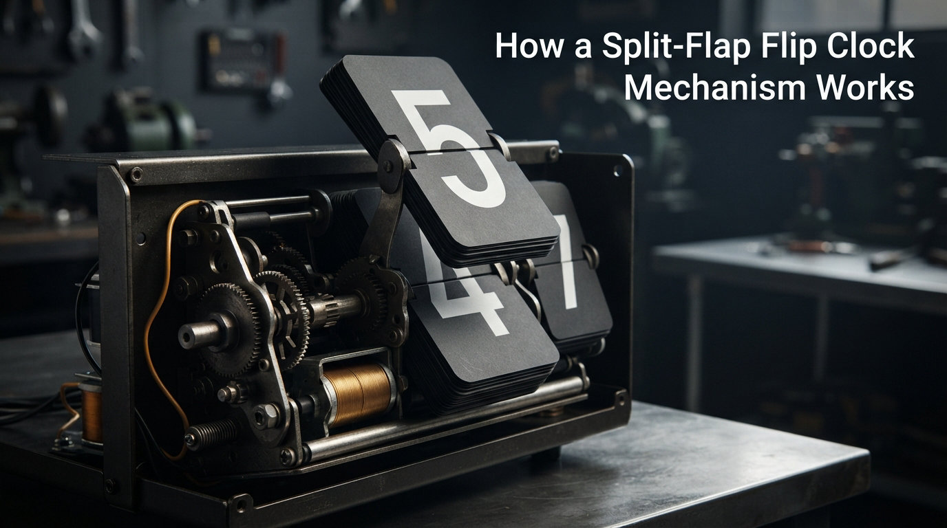
A split-flap flip clock mechanism is an electromechanical display device that shows changeable alphanumeric text by flipping printed flaps attached to a rotating spindle. The mechanism uses a stepper motor to rotate a drum of character-printed panels, and one panel falls flat against the next to reveal a single character while the rest stack tightly behind the display face. This simple but elegant approach powered train station departure boards, airport arrival signs, and the desk flip clocks that defined an entire era of mid-century design.
On our site at Exquisite Clock, we look at horology through every lens, from antique pendulums to electromechanical curiosities. The split-flap flip clock is one of the most loved, and most asked-about, displays on the internet. In this guide, I will walk you through how the mechanism actually works, what each component does, where the design came from, and why it is still popular in 2026.
Table of Contents
How a Split-Flap Flip Clock Mechanism Works Step by Step
The split-flap flip clock mechanism works by rotating a stack of character-printed flaps past a viewing window, then letting one flap fall flat to display a character while the rest stay neatly rolled. Each digit position is built around a vertical drum of flaps, and a stepper motor rotates that drum one increment at a time to advance the display.
Here is the sequence in plain language, the same way I explain it to readers who have never opened a flip clock before.
Step 1: The Motor Receives a Command
A microcontroller, quartz timekeeper, or mechanical mainspring sends a pulse to a small stepper motor. Each pulse corresponds to a single character advance. Most modern flip clocks use a 24-step stepper motor, but older units use a 12-step motor paired with a geartrain. The motor does not need to know which character is showing. It only needs to know how many steps to advance.
Step 2: The Spindle Rotates the Drum of Flaps
The stepper motor is mounted to a vertical spindle. The spindle carries a stack of 40 to 60 flaps, each printed with a character, number, or symbol. As the spindle turns, the flaps lift from the bottom of the stack and travel upward over the top of the display housing.
Step 3: One Flap Falls Flat to Display the Character
Right at the front of the housing, a stationary bar, often called a detent, holds back every flap except the very first one in the rotation. When the next flap reaches the bottom of the loop, gravity pulls it past the detent and it falls flat against the window. The casual user just sees a character change. The reality is a carefully timed mechanical dance.
Step 4: The Window Only Shows a Fraction of Each Flap
Each flap is printed with identical characters along its length, so as it falls flat, the top half displays the upper digit and the bottom half displays the lower digit. This is where the famous “split-flap” name comes from. Two flaps are visible at any time, stacked vertically, and the meeting line between them is the horizontal gap you see in the display.
Step 5: The Sequence Repeats For Each Digit
A flip clock has four of these drums, one each for tens-of-hours, hours, tens-of-minutes, and minutes. To advance one minute, the ones-minutes drum rotates one step. To advance ten minutes, the tens drum rotates one step and the ones drum rotates a full revolution. The hour drums follow the same pattern. This is why the clock has that lovely “thunk, thunk, thunk” rhythm as it ticks past the minute.
That five-step dance is the answer to the question “how does a split-flap flip clock mechanism work”. The rest of this article unpacks the components, the history, and the engineering details that make the design so satisfying.
The Core Components Inside a Flip Clock
Under the casework of any flip clock you will find a small family of mechanical parts. Each one has a clear job, and once you know what to look for, you can identify them at a glance, even in a thrift-store unit. Here are the parts that make the mechanism work.
The Stepper Motor
The stepper motor is the heart of a modern flip clock. It receives electrical pulses from the controller board and rotates a precise number of degrees per pulse. Common motors used in DIY projects are 28BYJ-48 unipolar steppers, which are inexpensive and produce enough torque to lift a full stack of flaps. Vintage flip clocks from the 1970s and 1980s often use a 12-volt DC solenoid instead and rely on a mainspring or pawl-and-ratchet system to advance the drum.
The Spindle and Drum Assembly
The spindle is the vertical shaft that carries the stack of flaps. Each flap is anchored to the spindle with a thin pin along the top edge. This pin is what allows the flap to pivot, so when one flap falls flat at the front, the others stay rolled and travel up the back of the drum. The flaps themselves are usually made of thin printed card or plastic, sometimes reinforced with a mylar coating for durability.
The Printed Flaps
Each flap is printed with two glyphs, one for the top half of the digit window and one for the bottom half. In a clock, the bottom half of the tens-of-minutes flap prints 0, 1, 2, 3, 4, 5, and the top half prints 0, 1, 2, 3, 4, 5 as well, so the display can show combinations from 00 to 59. On a station departure board, the flaps print letters, numbers, punctuation, and blank spaces, depending on the route.
The Detent and Stop Geometry
The detent is the unsung hero of the mechanism. It is a small metal or plastic lip at the front of the drum that holds the flaps in a tight roll. When the next flap reaches the front, the detent deflects slightly and lets the flap fall flat under gravity. Without the detent, the flaps would sag forward and the display would lose its crisp look. Getting the geometry of the detent right is one of the hardest parts of a DIY build.
Sensors for Position Feedback
Modern electronic flip clocks use a Hall effect sensor or a rotary encoder to keep track of where the drum is. The sensor triggers once per full revolution, so the controller knows which character is currently displayed. Without this feedback, the clock would lose track within a few hours and start showing the wrong time. Vintage mechanical units solve this problem with a Geneva drive and a physical stop.
The Driver and Microcontroller
In a modern electronic flip clock, the driver board receives commands from a small microcontroller, often an Arduino Nano or an ESP32. The controller receives time from a real-time clock (RTC) module, then pulses the correct stepper motor at the right moment. This is the layer that lets you build a DIY split-flap display for a few hundred dollars in parts.
The Power Supply and Wiring
Each stepper motor in a flip clock typically runs on 5 to 12 volts DC, and the microcontroller runs on a separate, lower-voltage rail. Most builders use a 5V power supply for the controller and a 12V supply for the motors, joined by a common ground so the logic signals stay clean. Power wiring is one of the most overlooked parts of a build, and a sloppy wiring job is the top cause of flicker, missed steps, and sensor dropouts in finished DIY clocks.
From Mainspring to Microcontroller: A Brief History of the Split-Flap Flip Clock
The split-flap display has a longer history than most people realize. The first designs predate the digital age by half a century, and the technology has gone through several distinct eras.
Josef Pallweber and the 1890 Patent
The earliest flip clock patent was filed by Austrian engineer Josef Pallweber in 1890. His design used rotating discs with numbers printed on the edges, and at each minute, the next disc would flip into view. Patents from this era show beautifully engineered devices that look surprisingly modern. Pallweber’s clocks were produced in small numbers and remain highly collectible today.
Mainspring and Solenoid Era (1950s to 1970s)
The split-flap display as we know it was popularized by Solari di Udine, an Italian company founded in 1957. Solari’s departure boards, often called “Solari boards”, became the standard at airports and train stations across Europe. The 1970s saw the rise of several competitors, including Pragotron in Czechoslovakia and Twemco in Hong Kong, which focused on smaller desk and wall flip clocks for home use.
Quartz and Integrated Circuit Era (1980s to 1990s)
By the 1980s, most flip clocks were driven by quartz crystals and integrated circuits. The Copal-made flip clocks sold in Panasonic and Braun product lines are now design icons. Their clean sound and visible mechanical action have earned them a cult following among collectors.
The Arduino and 3D Printing Revival (2010s to 2026)
The current era is the most exciting for hobbyists. Open-source projects from makers like Scott Bezek, Sven Braun, and the team at Parts Not Included have published complete designs, including 3D-printed flap assemblies, stepper motor control boards, and Arduino code. You can build a working split-flap clock for a few hundred dollars, and a full desk-sized display for around the cost of a mid-range laptop. This is why searches for “DIY split-flap display Arduino” keep growing year after year.
Where You Still See Split-Flap Displays Today
Even in the age of LCD and OLED, split-flap displays are still in service around the world. Their high visibility, wide viewing angle, and positive readability in direct sunlight make them hard to replace in some roles.
Train Stations and Rail Terminals
European rail stations were the original home of the Solari board. Many stations in Germany, Switzerland, Italy, and the Netherlands still use them for departure boards. The Amsterdam Centraal station, for example, kept its original board in service until the late 2010s. New York Penn Station’s “Solari board” became so iconic that it was preserved as a heritage piece when the digital replacement went in.
Airports and Gate Announcements
Airports continue to use split-flap boards for gate information, particularly in terminals that emphasize visual clarity. The boards are easy to read at a glance, even from 30 feet away, and they keep working through power glitches because the most recent displayed information is purely mechanical.
Game Shows and Live Events
Split-flap displays became a hallmark of game shows like “The Price Is Right” and “Klapper und Klapp” in Germany. The visible mechanical action creates anticipation, which is exactly what a live show needs. You can also find them on stage at concerts and conferences where organizers want to add a retro flavor to the production.
Modern Desk Clocks and Home Decor
The home flip clock market has grown steadily since 2015. Today, you can buy a new split-flap clock from brands like Twemco, Biegert & Funk, and a handful of small-batch makers. The appeal is partly nostalgia and partly the unmistakable “thunk” of the flap hitting the detent. We will not mention prices in this article, but you will find that the gap between a vintage secondhand unit and a brand-new maker-built clock is smaller than you might expect.
Split-Flap vs Flip-Dot vs LED: How the Mechanisms Compare
Split-flap displays are not the only electromechanical display technology. Two common alternatives are flip-dot displays and LED matrices. Each has very different trade-offs, and knowing them helps you understand why split-flap won its corner of the market.
Power Consumption
Split-flap displays use zero power when the display is static. The flaps simply rest where gravity puts them. Flip-dot displays also use no power when static, but they require a power pulse to flip each dot. LED displays consume continuous power, even when the displayed content does not change. For a 24-hour departure board, that difference adds up.
Readability and Viewing Angle
Split-flap displays have near-perfect readability in any lighting condition. They do not wash out in direct sunlight, and the contrast is essentially 100% black-on-white. Flip-dot displays are also highly readable, but the contrast is lower because the dot is recessed. LED displays offer variable brightness but suffer from glare in direct sunlight.
Sound and Atmosphere
Split-flap displays have a distinctive clatter that has become part of their identity. Flip-dot displays make a single click per dot change and are much quieter. LED displays are silent. For a setting where atmosphere matters, the split-flap sound is genuinely a feature, not a bug.
Maintenance and Lifespan
Split-flap displays require periodic cleaning and lubrication, plus replacement of worn flaps. A well-maintained unit can run for 30 years. Flip-dot displays have similar lifespans but are easier to repair at the dot level. LED displays have the longest theoretical lifespan but degrade gradually as individual pixels dim.
The Engineering Details Most Guides Skip
The basic mechanism is easy to understand, but the engineering details are what separate a smooth-running flip clock from a noisy one. Here are the deeper details that DIY builders spend the most time on.
Why the Flaps Fall Flat and Stay Flat
The flap pivot pin is offset from the center of the flap, so the weight of the flap acts as a restoring force. When the flap reaches the front of the loop, gravity pulls the heavy end forward, and the flap falls flat against the previous one. The detent keeps the roll tight, so the moment the leading flap clears the detent, the next one snaps flat.
Detent Geometry and Flap Spacing
The detent angle is critical. Too shallow, and the flaps do not release cleanly. Too steep, and the flap falls too fast and slams into the previous one. Most production flip clocks use a detent angle of around 20 degrees and tune the flap weight to match. This is the main reason a vintage flip clock sounds “right” – the geometry has been refined over decades.
Syncing Multiple Drums Together
When a clock displays 12:59 and the minute advances to 1:00, the tens-of-minutes drum must rotate from 5 to 0. The ones-minutes drum must rotate from 9 to 0 at the same time. The controller coordinates this by triggering both motors in parallel and using the sensor feedback to confirm both reached the new position. Misalignment between drums is one of the most common bugs in DIY builds.
Sound Generation and Damping
The split-flap sound is produced by the flap falling flat against the previous flap, the detent catching the next flap, and the motor itself. To soften the sound, some makers add felt pads at the front of the housing or use rubber dampers on the detent. Solari’s classic boards use a tuned detent geometry that produces a satisfying “chuff” rather than a sharp “click”. This is why audiophiles and clock fans alike describe the split-flap sound as iconic.
Wear Patterns on Long-Running Units
If you open a flip clock that has been running for 20 years, you will usually see wear on the detent and on the leading edge of the first flap. The motor gear may also have tooth wear. These are the parts that most often need replacement during a service. The flaps themselves are usually fine unless they get jammed and torn.
Tolerance and Calibration Challenges
Each drum must be calibrated so that the same character shows on every clock, even after hundreds of thousands of steps. Slight variations in flap thickness, detent angle, and sensor position all add up. Manufacturers compensate by tuning the gear ratio and the motor drive voltage. DIY builders often need to experiment for a few hours before each module displays crisply, and this is one of the reasons the build process is so rewarding.
Modern DIY and 3D-Printed Split-Flap Projects
The split-flap flip clock has had a strong DIY revival since 2015. Open-source projects have made it possible for individual makers to build impressive displays at home, and the cost has come down significantly. Here is what you can expect if you decide to build one yourself.
The Most Popular Open-Source Builds
The Parts Not Included split-flap display is one of the most cited DIY projects, with full schematics and code released on GitHub. The Scott Bezek build, popular on YouTube, focuses on a smaller single-digit module that can be tiled. Several other makers have published variations on Hackaday and Hackster. These projects typically use 3D-printed flap assemblies, NEMA 17 stepper motors, and Arduino or ESP32 controllers.
Typical Component Costs and Build Time
A single-digit module can be built in under a weekend for the cost of a stepper motor, an Arduino, and a handful of 3D-printed parts. A full four-digit desk clock takes around 40 to 60 hours of build time spread across several weekends. A wall-mounted display with 16 or more modules is a serious project that takes a few months of evenings and weekends.
Why Hobbyists Keep Coming Back
DIYers say the appeal is the combination of mechanical engineering, electronics, and software. Each subsystem is simple, but together they produce a result that feels alive. The mechanical action also makes the clock feel like a piece of furniture rather than a piece of electronics, which is rare in 2026.
Where to Find the Community
The Reddit r/arduino, r/3Dprinting, and r/DIY communities are active with split-flap build logs. The NAWCC forum at mb.nawcc.org is the best place for vintage flip clock repair questions. GitHub has dozens of public repositories with parts lists, code, and 3D-print files. If you want to build one, you are not alone and you do not have to start from scratch.
Frequently Asked Questions
How does a flip clock work?
A flip clock works by rotating a stack of character-printed flaps past a viewing window using a stepper motor or solenoid. Each flap is hinged at the top, and gravity pulls the leading flap flat against the previous one to display a single character. Four of these stacks side by side form the hours and minutes of a clock.
What is a split-flap display?
A split-flap display is an electromechanical display device that shows changeable alphanumeric text by flipping printed panels attached to a rotating spindle. Each panel has a glyph on its top half and another on its bottom half, so two panels stacked at the front can display any pair of characters. They were widely used for train and airport departure boards.
Who invented the flip clock?
The earliest flip clock mechanism was patented by Austrian engineer Josef Pallweber in 1890. The modern split-flap display as we know it was popularized by Solari di Udine in Italy in the 1950s, with companies like Pragotron and Twemco following in the 1970s and 1980s.
Why are flip clocks so expensive?
Flip clocks are expensive because each unit contains 40 to 60 precisely printed flaps, a stepper motor or solenoid, a spindle assembly, and a tuned detent. The mechanical tolerances are tight, and the parts are not mass-produced in the same way as LCD displays. Vintage units in good condition are also rare, which raises prices further.
How do departure boards work?
Train station and airport departure boards use the same split-flap mechanism as a flip clock, but with many more modules. Each row of the board is a long chain of characters, each on its own drum. A central controller advances each drum independently to spell out destinations, times, and platform numbers.
What is the sound split-flap displays make?
The split-flap sound is a short clatter produced by the flap falling flat against the previous flap, the detent catching the next flap in the stack, and the motor advancing. The pitch and duration vary with the size of the flaps and the geometry of the detent. The sound has become iconic and is part of the appeal of the technology.
Conclusion
Now you know how a split-flap flip clock mechanism works, from the motor command to the final flap falling flat. The split-flap flip clock is a beautiful example of electromechanical design that has stayed relevant for over a century. If you want to see one in person, visit a major European train station or hunt for a vintage Twemco or Copal unit at your local antique shop. If you want to build one, the open-source community has done most of the hard work for you.
For more on how clocks work, how they are made, and how to keep them running, keep exploring Exquisite Clock.